(Quick Guide) CAN /CAN-FD Debugging

- INTRODUCTION
- Project Overview : Overview on Debugging of CAN / CAN-FD BUS
Debugging of CAN (Controller Area Network) and CAN-FD (Flexible Data-rate) in a system is a critical aspect of ensuring smooth and reliable communication between the electronic components. One common issue that can arise during debugging is signal integrity, which can cause errors in the transmission and reception of data. It is also important to check the configuration and settings of the CAN/CAN-FD controllers, such as the bitrate and sample point, to ensure they are properly set up. Additionally, analyzing the bus traffic and using debugging tools, such as oscilloscopes and logic analyzers, can help identify and isolate issues. By carefully debugging the CAN/CAN-FD system, you can ensure optimal performance and avoid potential errors or malfunctions.
- Detailed description of components :
- tested on STM32H7XX
- Code generated through CubeMx (see reference for more detail)
- Safety Requirement :
- Debugging of CAN BUS :
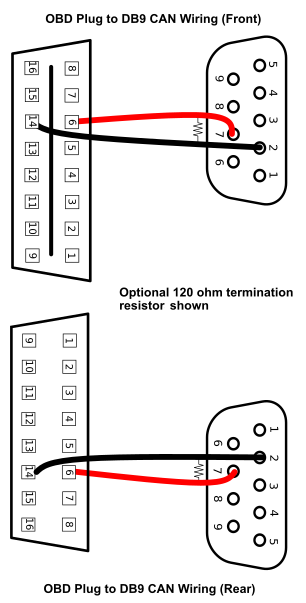
- CAN BUS need to be transmitted with the impedance of of 120 Ohm. At the end of the system.
- CAN bus connection need to be done in daisy chain mechanism (it is recommended).
- Go with the twisted pair wire or shielded twisted pair wire.
- Connector recommended is Deutsche Plug Connector
- CAN-H (voltage level) : 2.5v to 3.5v
- CAN-L (voltage level) : 1.5v to 2.5v
- While on multimeter on a working connection the voltage of (depending on the bandwidth or bus load):
- CAN H slightly above 2.5v
- CAN H slightly below 2.5v
- Termination register is important to avoid back propagation of signal.
- The stub or extension wire need to be shorter than the main wire to avoid noise in the signal.
- The wire resistance between a working CAN circuit need to be 60 ohm(recommended), it can be 40 ohm (not recommended).
- Some device have the termination resistance build in which is software configurable or can be tested when the device is power on.
- If the
CAN-HandCAN-Lare connected reverse then the voltage in CAN-L will be higher than CAN-H. - The proffered way of debugging a CAN circuit is to check each CAN device one by one.
- If any of the CAN Signal is grounded than the overall voltage will drop regardless of CAN-H and CAN-L.
- The impedance between CAN wire and ground should in M ohm (open-circuit).
- visit this site for the selection of the time quanta : http://www.bittiming.can-wiki.info/
- And for FD-CAN use this software: https://www.peak-system.com/fileadmin/media/files/BitRateCalculationTool.zip
- Calculation of time quanta
1APB1 CLK(PCLK1) = 25 Mhz 2CAN Pre-scaler = 1 3Duration of 1 time quanta (1TQ) = PCK1 / CAN_pre-scaler 4 = 0.04 micro seconds - Always check for the clock frequency of the APB1 bus and configure your system according to that.
- TODO : Try this config (untested)

- Debugging of CAN BUS :
- Project Overview : Overview on Debugging of CAN / CAN-FD BUS

REFERENCE AND ADDITIONAL MATERIAL :
- See this youtube video for troubleshooting guide : Link
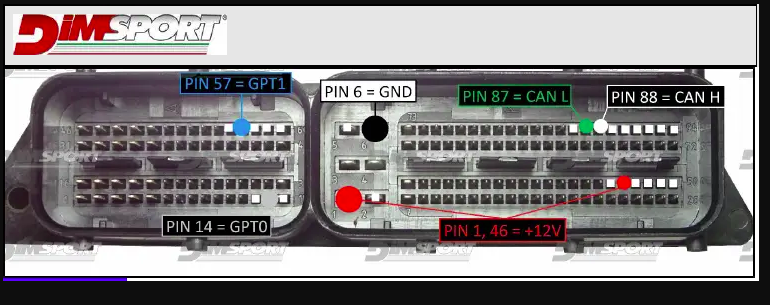
- Bosch ecu EDC17C53 Connection : Link
- CAN-FD documentation : Link
- Explanation of CAN-FD calculation : Link
- Official documentation guide : Guide
- Bosch reference of CAN-FD with example code: Link